
Odometry optimisation
Hi All
I have been playing with ROS1 for 6 weeks or so.
I have a robot built - 2 motors and a caster - differential drive, pi 4 (no arduinio etc), motor controllers, 2 x wheel encoders, ld19 lidar, ICM20948 IMU.
I have Ubuntu 20.04 on the Pi and on a virtual machine on the laptop, ROS Noetic installed on both, a driver node and odom node written, ld19 and imu drivers working into ROS.
My (I say my, mostly used from various tutorials) code is all here: https://github.com/KevWal/ROS-Bot-Wor...
More info here: https://answers.ros.org/question/4176... and here: https://answers.ros.org/question/4176...
I want to get it navigating from a Pose estimate to a Nav Goal, based on a pre built map, but am having trouble due it seems to poor odometry.
I have a couple of videos here:
https://www.youtube.com/watch?v=JPdHX... https://www.youtube.com/watch?v=fkxcI...
and numbers in a spreadhseet here: https://github.com/KevWal/ROS-Bot-Wor...
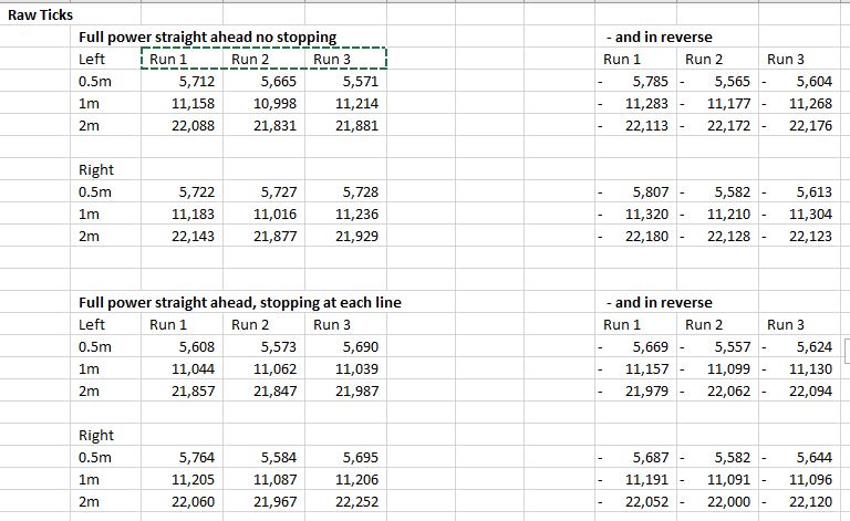
The raw values in the spreadhseet are:
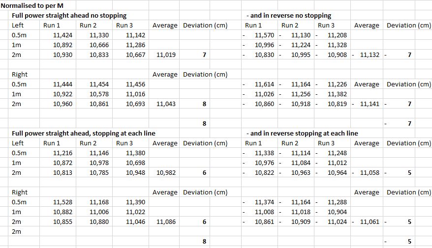
The values normalised to all be for the equivilent to 1m to all be comparable are:
Summary is in forwards and backwards movements my reported distance is out by a maximum of 8cm in a meter over 18 readings across both wheels. The only thing I can think to do from here is have slightly different encoder ticks per m values for the L and R wheels. 11,048 ticks per m for L and 11,083 for the right, but thats only 1/2 a cm difference?
Edit 1:
Doing some more testing, running each wheel for a fixed 10 turns, totally outside of ROS, and counting the encoder ticks. '10 turns' is judged by eye so will have a little variance. Because of slight differences in the motors 10 turns of motor L cant be assumed (isnt) 10 turns of motor R.
Lightly highlighted sections are those that match the 10 turns of that wheel. Bright yellow highlighted sections are areas of concern.
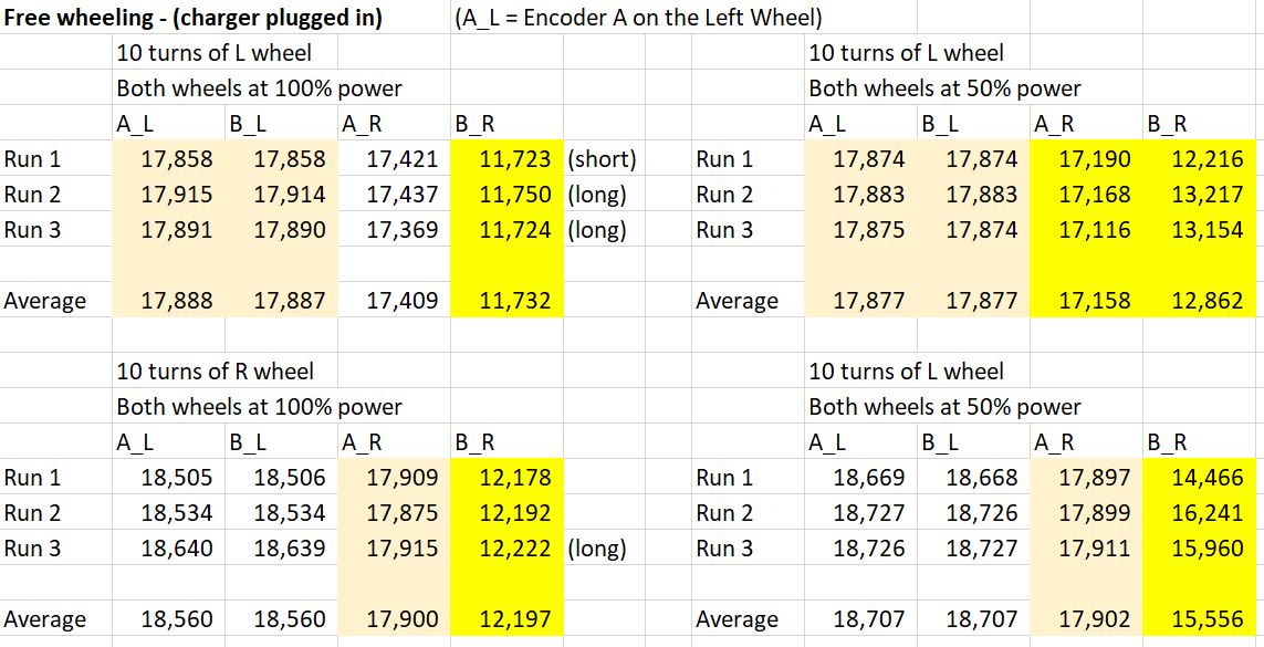
Clearly my B encoder of the Right motor has some serious issues. But I also have a whole set of readings on my A encode of the Right motor that are a good 250 ticks short too.
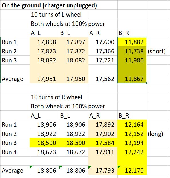
In my 'on the ground' tests I still have the B encoder of the Right motor issue, but I also have 1 line of readinds across all encoders on both motors that is a bit haywire.
Edit 2:
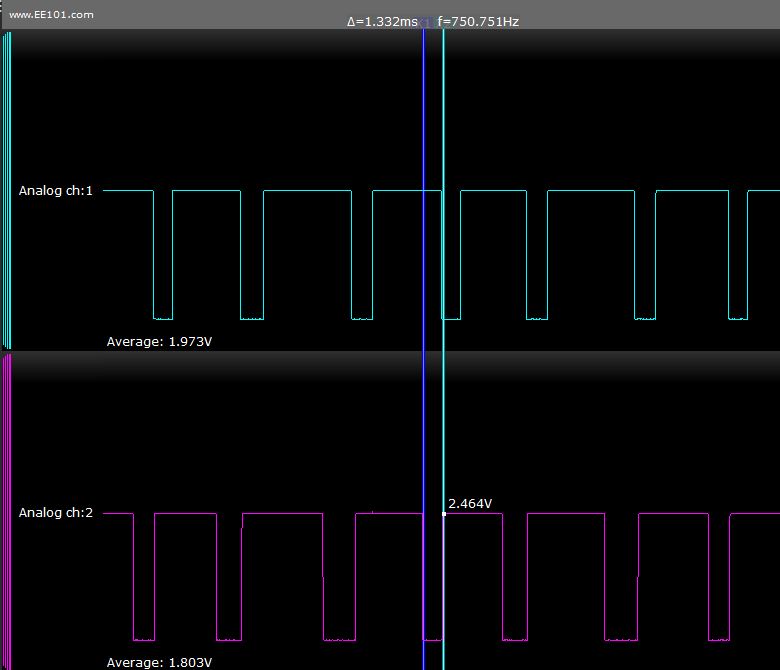
An osciliscope of Motor L (recording at 50Khz) generally looks good, signal voltage for a 3.3v signal is perhaps a bit low at 2.4v for a high? A few of the pulses are a bit different in length - generally 1.3ms but some are 2ms. Some corelation with every third pulse - and given the encoder is 3 magnets maybe one is a bit stronger than the others?
And on M R we clearly have periods of missing pulses on ...

How can 1 meter travel be less than both 0.5m and 2m travel as shown in your 1st, 2nd, and 6th forward trials and 1 meter travel be greater than 0.5m and 2m in the 2nd and 3rd backward trials? And what are the numbers in the table? Are these numbers in the registers(encoder counts)? If so what are the values at zero meters? It looks like you significant issues even beyond the significant 8% error noted(and 8% linear error is huge when you convert to rotation).
Hi Billy, In the table I have pasted above all the values are normalised to a self contained 1m. ie if they are 0,5m they are multipled by 2, if they are a reading subsequent to the first reading then they have the previous readings taken away from them - so every number is a comparable to every other.
The original values are in the xls I link to above.
Yes these are encoder counts counted at the output of the topic - /lwheel_ticks and /rwheel_ticks.
Every test started at an encoder count of zero and there are 12 tests above (3 tests full power ahead, 3 tests full power stop start ahead, 3 tests full power reverse, 3 tests stop start reverse).
When I say "full power " vs "full power stop start", I mean on "full power" I kept the stick pushed forwards and just marked the encoder reading at ...(more)
Looking at these normlaised encoder ticks per m values, reguardless if they are a true meter run, a 0.5m run scaled up, the start, middle, or end of a continuious 2m run, there are some big ish inconsistencies.
For example, the 0.5m to 1m part of run 2 and run 3 for full power no stopping - the equvilent of 10,666 ticks vs 11,286. Why does the same 0.5m traveled sometimes show 620 less ticks - the equivilent of 5cm difference!
I am pretty sure this is not wheel or tire slipage - there is nothing holding the robot back.
Next test is off the ground I think - how many ticks for ten visual rotations of the tire, totally isolated from ros, just make the motor go full power and count the ticks for 10 rotations. One for the morning.
+1 for planning isolation testing. Do you have an oscilloscope you can use to look at raw electrical signal? I'm suspecting you may find the signal drops out sometimes.
Some thoughts:
Hi Mike thanks for your questions:
Thanks very much Kev
A slight oddity, with the econders connected to the Pi and my DSO, I see highs of 2.4v on an analog reading, and I need to set the DSO to 1.8v logic in order for it to recognise that as a high. When I disconnect the encoder outputs from the Pi and just connect them to the DSO, I see highs of 3.3v and the DSO recognises that as High with a 3.3v logic setting (or infact any of the 1v, 1.8v, 2.5v, 3.3v, or 5v settings). I have tried playing with the pull up / pull down / float settings of the Pi DigitalInputDevice(encoder_a_l, pull_up=True) etc) to no effect at all.
Looks like you found the issue. Your right encoder is failed.